How to Cut an H-Beam with a CNC Plasma Cutter: Step by Step
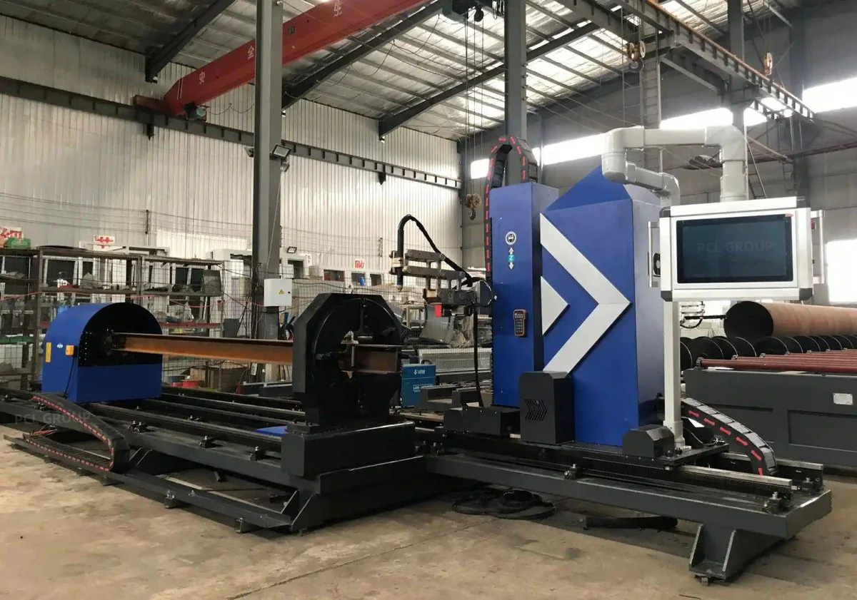
Short answer
- Measure the real section first: rolled H-beams vary from nominal in depth, flange tilt and web offset.
- Cut holes and inner contours first, copes next and the cut-off last, so the part stays supported.
- Weld access holes have minimum sizes in AISC 360 J1.6: length at least 1.5 times the web thickness and not under 38 mm.
- Check hole positions, cope depth and bevel angle on the first part before running the batch.
Before cutting: section, file and machine
| Check | Why it matters |
|---|---|
| Section size and grade | HEA, HEB, HEM, W or UB; the flange thickness sets plasma current and speed |
| Part file | DSTV (NC1) from Tekla Structures or Advance Steel carries contours, holes and marks for each face |
| Plasma source and consumables | Matched to the thickest flange; worn nozzles widen the kerf and spoil holes |
| Bed and supports | Long beams need support along their length so they do not sag under the torch |
Typical flanges: HEA 300 is 14 mm, HEB 300 is 19 mm, HEM 300 is 39 mm. A HEB 300 flange is a comfortable cut for a 200 A high-definition source; HEM sections push towards the top of plasma range or into oxy-fuel. The steel beam size chart lists the rest.
Step by step
- Load the beam web vertical on the infeed, with the reference flange against the datum.
- Measure the section. The machine probes or scans height, flange width, flange tilt and web offset. EN 10034 allows rolled H-sections to vary from nominal, and that variation moves holes and copes if the program assumes a perfect beam.
- Load the DSTV file and let the software map each contour to the web or a flange, apply kerf compensation and place lead-ins.
- Cut inner features first: bolt holes, slots and web openings, while the part is still fully supported by the rest of the bar.
- Cut copes and access holes next, then bevels.
- Cut the part off last. On machines that cut to the end of the bar, the next part starts from the same cut, with no tail-end scrap.
- Mark part number and fit-up lines with the plasma at low current, if the job calls for it.
Pierce, lead-ins and kerf
- Pierce in the scrap: start each hole and inner contour inside the area that falls out, then run onto the line, so the pierce crater does not land on the part.
- Edge starts where possible: copes and cut-offs can start from the flange edge, which is easier on the consumables than a pierce through a thick flange.
- Kerf: on thick flanges a plasma kerf is about 2-4 mm. The software offsets the path by half the kerf; a worn nozzle widens it and makes holes oversize.
- Good side: one side of a plasma cut is closer to square than the other. Set the cut direction so the square side stays on the part.
Weld access holes and copes
Weld access holes (rat holes) let a welder run a complete-penetration flange weld past the web. AISC 360 Section J1.6 sets their minimum size:
| Dimension | Minimum (AISC 360 J1.6) | Example: HEB 300 web, 11 mm |
|---|---|---|
| Length from the weld root | 1.5 × web thickness, and at least 38 mm (1.5 in) | 38 mm (1.5 × 11 = 16.5 mm, so the 38 mm minimum governs) |
| Height | Web thickness, and at least 19 mm (3/4 in); need not exceed 50 mm (2 in) | 19 mm |
| Radius at re-entrant corners | At least 10 mm (3/8 in), smooth, no notches | 10 mm or more |
Copes follow the same rule for re-entrant corners: cut a radius, not a sharp corner, because a notch at the corner of a cope is where cracks start. The weld access hole and coping guide shows common shapes.
Flange bevels
Moment connections need full-penetration welds on the flanges, usually with a single bevel of 30-45° and a small root face, as set by the welding procedure. A plasma beam cutter with a tilting torch cuts the bevel after the cope, in the same set-up. On thick flanges expect light grinding of the bevel face before welding. Bevel types are covered in beam bevel cutting.
Common faults and how to fix them
| Fault | Likely cause | Fix |
|---|---|---|
| Holes in the wrong place on the flange | Section not measured; flange tilt or web offset ignored | Probe or scan the beam before cutting |
| Oversize or tapered holes | Worn nozzle, hole too small for the flange | Change consumables; drill holes under 1.5× thickness |
| Dross on the underside of the flange | Speed or current wrong for the thickness | Use the cut chart for the flange, not the web |
| Cope edge notched at the corner | Sharp re-entrant corner in the program | Add a radius of 10 mm or more |
| Part length short | Kerf compensation or datum wrong | Check offset and reference flange |
| Beam moves during cutting | Clamping or support missing near the cut | Support both sides of the cutting zone |
Checks before the part leaves the machine
- Length: against the drawing, measured on both flanges.
- Hole positions and diameters: gauge lines and pitch with a tape and a pin gauge.
- Copes and access holes: depth, length and corner radius.
- Bevels: angle and root face with a welding gauge.
- Edge condition: dross removed, no notches at re-entrant corners.
- Marking: part number legible and on the right face.
When to move from plasma to laser
Plasma covers most H-beam work in buildings and industrial structures. A fiber laser pays off when beams carry many small bolt holes, slotted holes or bevels that must go straight to welding, or when visible steelwork needs a fine edge. For that work see the H-beam laser cutting machine; for high-throughput coping of H, I, U and L sections on a plasma coping machine, the H-Series robotic beam coping machine; and for beams plus pipe on one machine, the 8-axis robotic plasma beam cutter.
Machines mentioned in this article
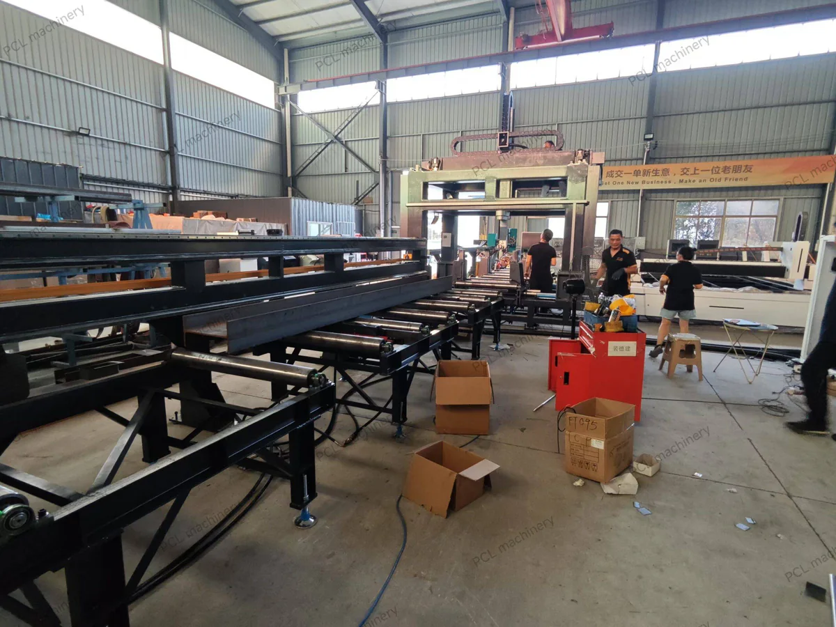
H-Series Robotic Beam Coping Machine
Plasma and oxy-fuel for H, I, U and L.
Compare all models8-Axis Robotic Plasma Beam Cutter
Beams, box sections and pipe.
View machine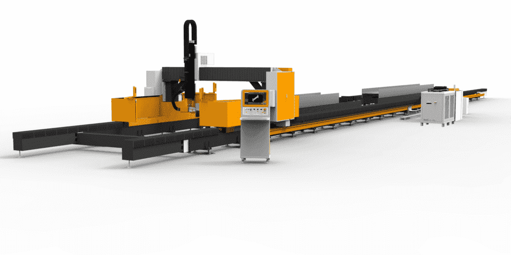
H-Beam Laser Cutting Machine
Fine holes and ready-to-weld bevels.
View machineAll Beam Cutting Machines
Laser, plasma and production lines.
View machineFAQ
How do you cut an H-beam with a CNC plasma cutter?
Load the beam, measure the real section, load the DSTV file, cut holes and inner contours first, then copes and bevels, and cut the part off last.
What order should features be cut in?
Inner features first while the part is fully supported, copes and access holes next, bevels after that, and the cut-off last.
What size should a weld access hole be?
Under AISC 360 J1.6 the length is at least 1.5 times the web thickness and not less than 38 mm, the height at least the web thickness and not less than 19 mm, with a radius of at least 10 mm.
Why measure the beam before cutting?
Rolled H-beams vary from nominal in depth, flange tilt and web offset within EN 10034 tolerances. Measuring keeps holes and copes in the right place on the real beam.
What plasma current cuts a HEB 300 flange?
The flange is 19 mm, so a source of about 130-200 A gives a production cut. HEM sections with 39 mm flanges need about 400 A or oxy-fuel.
How wide is the plasma kerf on an H-beam?
About 2-4 mm on thick flanges. The CNC offsets the path by half the kerf so parts are to size.
Why do copes need a radius at the corner?
A sharp re-entrant corner concentrates stress and can start cracks. A radius of 10 mm or more is standard practice.
Can a plasma beam cutter cut flange bevels?
Yes, with a tilting torch. Bevels of 30-45 degrees for complete-penetration flange welds are cut in the same set-up, with light grinding on thick flanges.
What file format do beam cutters use?
DSTV (NC1) files exported from Tekla Structures, Advance Steel or other detailing software.
Plasma or laser for H-beams?
Plasma for thick flanges and lower machine cost; laser for many small holes, slots and weld-ready bevels.