Robotic Welding & CNC Cutting for Steel Structures
Compare cutting and welding systems for beams, pipes and plate, from drawing review and weld preparation to installation and service.
Robotic vs. Manual Welding
Use the same drawing, material and batch size to compare from first fit-up to accepted parts.
| Factor | Manual | Robotic |
|---|---|---|
| Speed | Time fitting, tacking, welding and repositioning. Include cleanup on the finished part. | Time setup, seam finding, loading and unloading as well as the welding cycle. |
| Consistency | Check how different shifts handle tack placement, joint gaps and torch access. | Prove the fixture and sensing on parts at both ends of the expected fit-up range. |
| Safety | Plan extraction, arc screening, work positioning and handling of hot steel. | Review fencing or safeguarding, extraction, interlocks and safe access for loading. |
| Staffing | Account for fitting, welding, lifting and inspection on each shift. | Account for setup, programming, loading and inspection. Confirm operator coverage during the trial. |
| Material and rework | Record wire use, grinding time and rejected joints per accepted part. | Track the same measures over multiple batches, including restarts and any repairs. |
Versatile Welding Modes
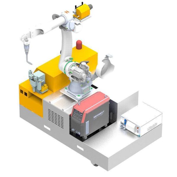
Start with the joint drawing and approved welding procedure. Then check torch access and how the workpiece will be held or turned.
MIG / MAG
Evaluate MAG for carbon-steel brackets, stiffeners and beam assemblies with repeatable fillet or groove welds. Use the approved procedure to define wire, gas and welding position.
- Check whether the torch clears the web, flange and fixture.
- Include joint preparation, tack placement and the required weld size in the test.
- Review turning and re-clamping for work with seams on several faces.
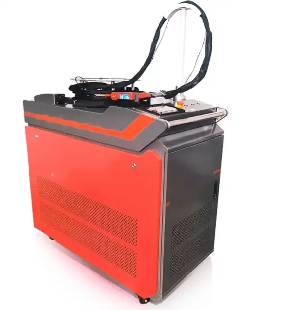
Fiber laser welding
Evaluate thin sheet and accessible seams where parts can be held in close alignment. Use the actual alloy, thickness and edge preparation in the trial.
- Check seam gaps, clamp clearance and joint accessibility.
- Inspect the weld and measure distortion after unclamping.
- Confirm weld acceptance criteria, shielding and laser guarding with the selected system.
Multi-process fabrication
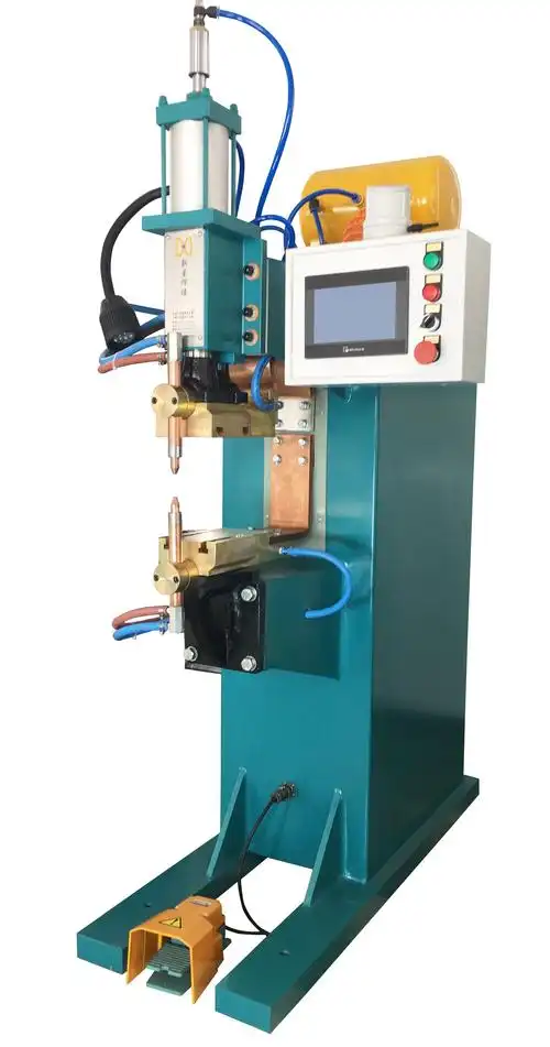
Plan each joint around its approved procedure. If the job needs a separate TIG or hybrid stage, confirm equipment compatibility and how the work transfers between stations.
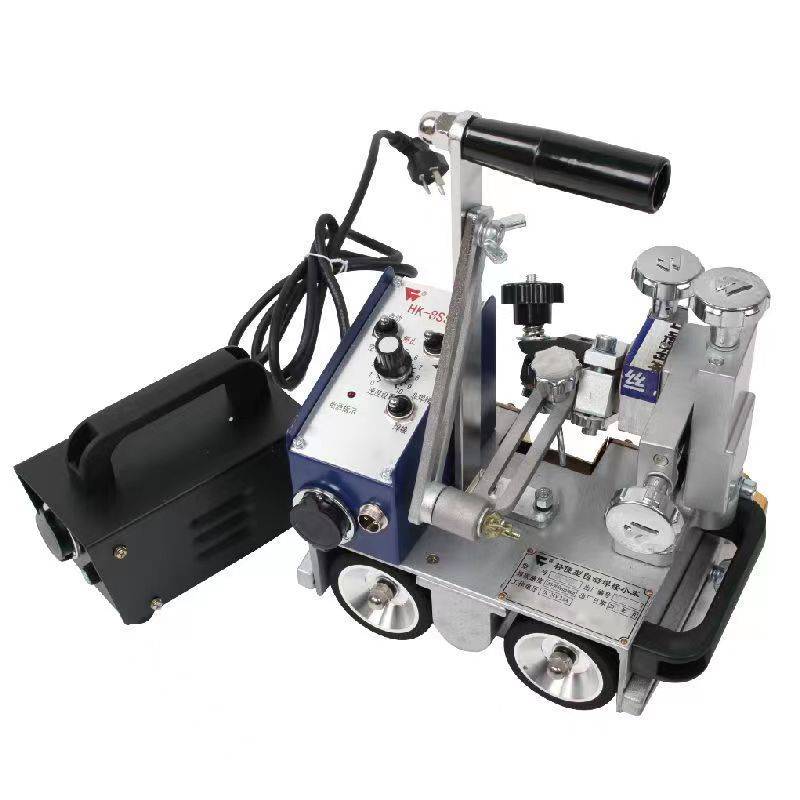
- Group repeatable seams for the robot and identify joints that need a different process.
- Check fixture changes and how the operator verifies the first part after changeover.
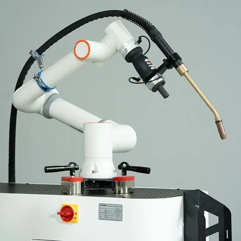
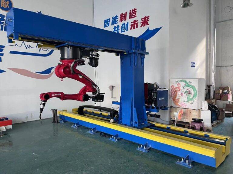
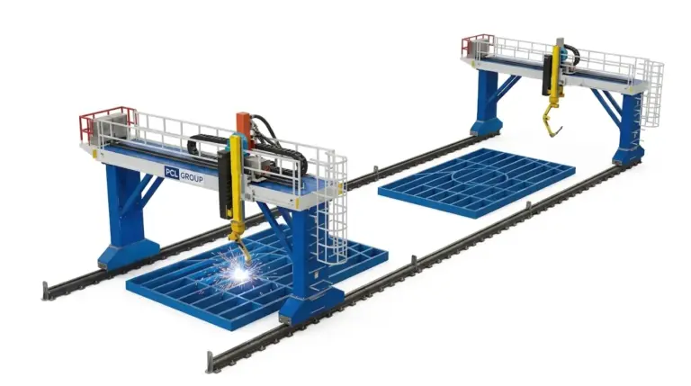
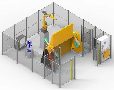
- Compare a cobot, a fixed cell with a positioner and a gantry using the same part drawing.
CNC Cutting Models
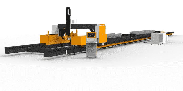
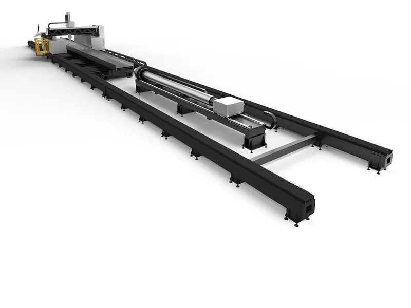
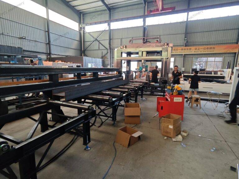
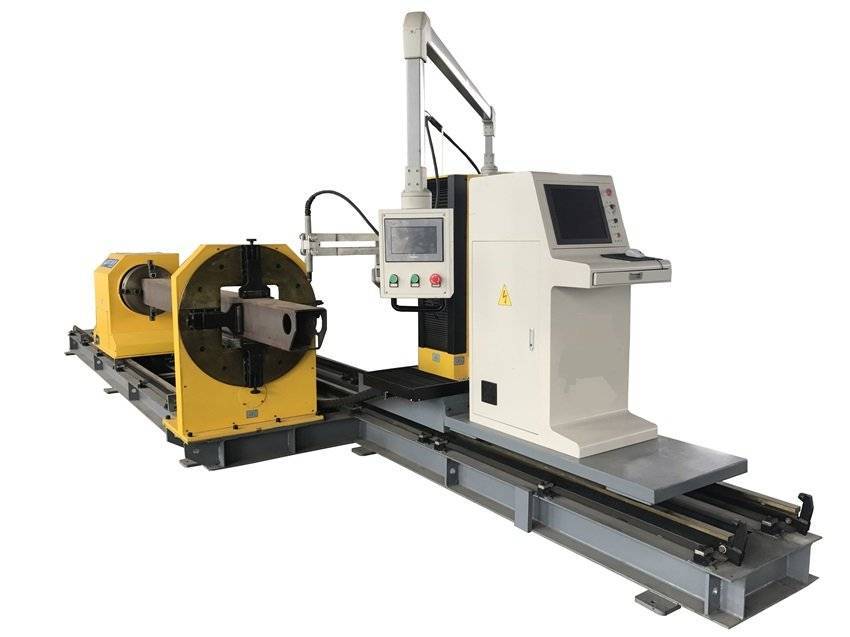
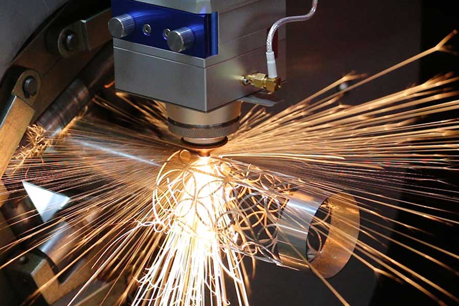
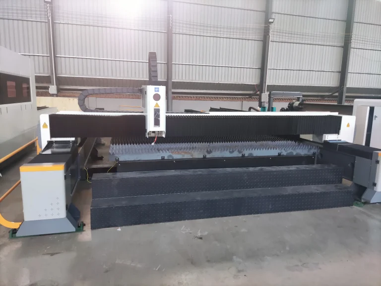
Choose by workpiece. Beams need access to web and flanges, pipe needs rotation and support, and flat plates need a suitable cutting bed.
Select Equipment by Workpiece
Start with a typical part and the hardest part in the order. Confirm both before specifying the machine.
| Workpiece | Equipment to compare | What to prove on the trial |
|---|---|---|
| Beams and channels | Beam laser cutting or plasma beam coping | Import a representative DSTV file. Check copes, bolt holes, underside clearance, bevels and marks against the drawing. |
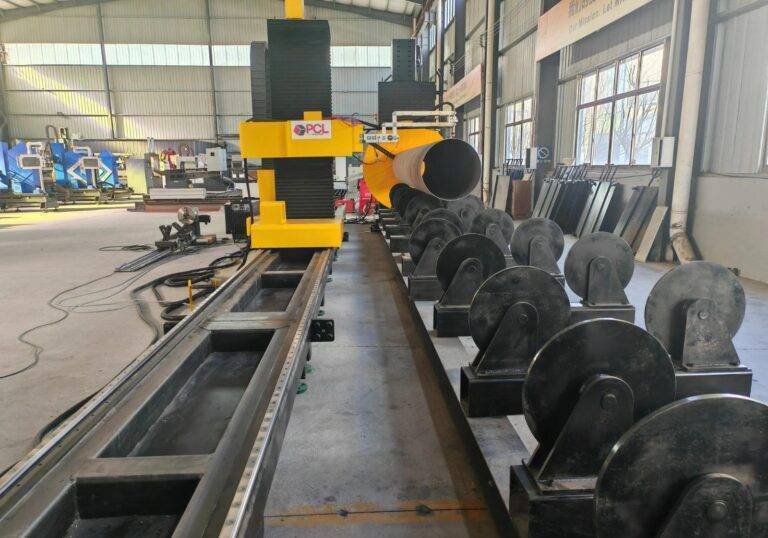
| Pipe and hollow sections | Tube laser cutting or pipe cutting and beveling | Check outer diameter, wall thickness, length and weight. Run the branch cut and bevel through rotation with the intended supports. |
| Plate components | Gantry laser or gantry plasma and oxy-fuel | Specify material, thickness, bed size, the smallest required hole, piercing method and edge acceptance. |
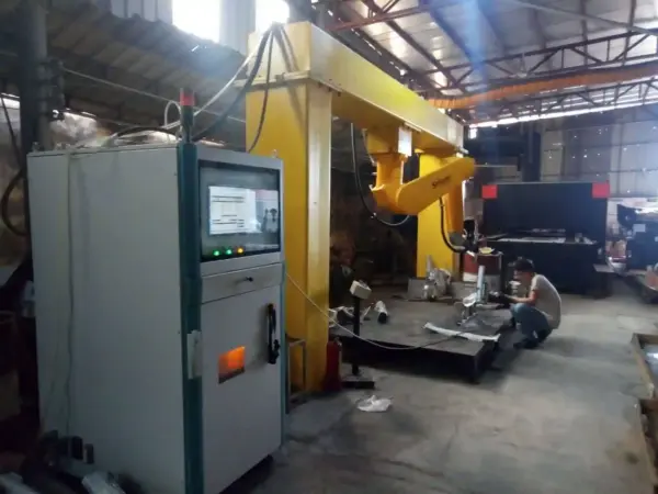
| Welded frames | Cobot, cell with positioner or gantry robot | Review assembly mass, fixture access, joint locations and changeover. Verify the complete seam sequence on a tacked part. |
The 5-axis beam laser and large-diameter rotary pipe cutter each list bevels up to ±45° for their own workpiece geometry. Confirm the joint profile, root face and required angle on the drawing.
See the DSTV-to-beam workflow, V, Y and K beam bevels and pipe profile examples for drawing and sample checks.
After-Sales & Logistics Support
From factory packing in Jinan through commissioning, operator training and service after handover.
Reinforced packing
For export shipments, review reinforced wooden crating, moisture protection and how long rails or removable assemblies will be secured. Check the crate dimensions, lifting points and unloading plan before dispatch.
Installation and training
PCL offers on-site installation and operator training. Confirm site preparation and utilities in advance. Use the first trial part to cover setup, routine maintenance and what to check when an alarm stops the machine.
Spare parts and consumables
Match the first stock of consumables to the installed torch or welding process. Record order codes, replacement intervals and expected supply times for critical parts.
Technical support after handover
Confirm the support contact, remote diagnostics, warranty coverage and software support for the specified configuration. Keep a backup of programs and controller settings.
See PCL packing and service and factory support and operator training.
Integrated fabrication in operation
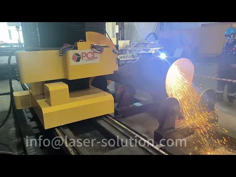
Watch how the pipe is supported and rotated through the cut. For a weld preparation trial, check the contour, bevel and root face on your pipe drawing.
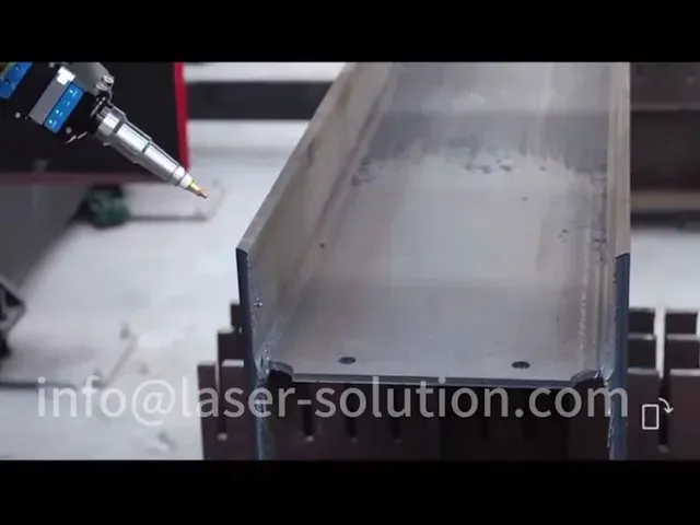
Look at the openings and profile cuts, then verify cutter clearance at the flange and web. Use a sample DSTV file to check nesting, copes and weld access holes.
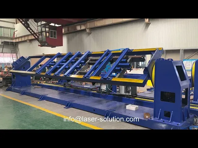
See how the positioner presents the assembly to the robot. Check whether the same positioning and seam order are suitable for your fixture and joint geometry.
Frequently asked questions
Can I use Tekla DSTV files for beam cutting?
Some beam cutting configurations support DSTV files. Send a sample export with your copes, holes and bevels so PCL can confirm what the selected control and software will import. For plate work, include a representative DXF if available.
How do I choose between laser, plasma and oxy-fuel cutting?
Start with the material, thickness, features and required edge condition. Compare laser for fine details and narrow kerfs, plasma for plate and profile work where its edge quality is acceptable, and oxy-fuel for thick carbon steel. Ask for a sample cut before selecting the process.
How thick a plate can the machine cut?
The limit depends on the material, the power source, whether the part must be pierced, and the edge quality required. Send the maximum thickness and cut features so PCL can review the configuration and a suitable test.
Can the machine cut weld-ready bevels?
Bevel capability depends on the cutting head, workpiece geometry and material thickness. Send the bevel angle, root face and joint detail. Check the cut and fit-up on a representative part before committing to a production setup.
When should I choose a cobot, a welding cell or a gantry?
Start with part size, presentation, seam access and repeatability. Consider a cobot for fixtured jobs that change often, a dedicated cell for repeat batches, and a gantry for large or long assemblies. Include positioners, guarding and loading in the layout review.
Can installation and operator training be included?
Discuss commissioning, training, spare parts and service scope when requesting the quote. The delivery and support arrangements depend on the machine configuration, workshop location and site conditions.
Send a part drawing for review
Tell us what you make and which stage is the bottleneck. A representative part helps us review machine options and plan a useful test.
- Material, thickness and largest part dimensions
- Cut features, bevels or weld joints
- Batch size or target quantity per shift